ROCK-SOIL ENGINEERING

Calculation and Analysis of Load-Reduction Effect of Integrated Support Structure of Precast Piles with Dentiform Curtains

  • LI Yong-hui , 1 ,
  • YU Ding-jiang 1 ,
  • ZHANG Ding-hao 1, 2 ,
  • ZHANG Yi-fan 1 ,
  • ZHANG Xin 1
Expand
  • 1 College of Civil Engineering, Zhengzhou University, Zhengzhou 450001, China
  • 2 Henan Transport Investment Group Co., Ltd., Zhengzhou 450016, China

Received date: 2025-03-07

  Revised date: 2025-06-18

  Accepted date: 2025-07-09

  Online published: 2025-09-01

Abstract

[Objective] The integrated support structure of precast piles with dentiform curtains can effectively reduce the earth pressure acting on the support structure and enhance its overall performance. This study aims to quantitatively analyze the load-reduction characteristics of the dentiform walls in this structure, reveal the key mechanisms of load reduction, and provide a theoretical reference for the design and calculation of this novel composite support technology. [Methods] Based on the load-reduction mechanisms of the dentiform walls in an integrated support system of precast piles with curtains, a cycloidal slip surface conforming to the actual sliding failure mode of the soil behind the walls was introduced. A calculation method for the load-reduction effect of the dentiform walls under soil sliding conditions was developed using the horizontal thin-layer differential theory. Based on the validation through calculation examples, the impact of key parameters—including dentiform wall structural parameters (spacing, width, thickness), soil strength parameters (cohesion, internal friction angle), and soil-wall interface strength parameters (soil-wall cohesion, soil-wall external friction angle)—on the load-reduction effect of earth pressure was further analyzed. [Results] When the dentiform wall spacing decreased from 3 m to 1.2 m, the load-reduction ratio increased from 23.77% to 44.02%. When the dentiform wall width increased from 0.5 m to 3 m, the load-reduction ratio increased from 17.16% to 46.34%. When the dentiform wall thickness increased from 0.4 m to 1.0 m, the load-reduction ratio only increased from 32.66% to 36.66%. When soil cohesion (c) increased from 1 kPa to 16 kPa, the load-reduction ratio increased from 28.14% to 59.86%. When the soil internal friction angle increased from 16° to 31°, the load-reduction ratio increased from 20.43% to 42.68%. When the soil-wall interface cohesion (c1) increased from 0.6 kPa to 9.6 kPa, the load-reduction ratio increased from 27.41% to 50.41%. When the soil-wall interface external friction angle increased from 9.6° to 18.6°, the load-reduction ratio increased from 30.33% to 36.21%, with the rate of increase gradually slowing down. [Conclusion] The developed calculation method effectively solves the problem that earth pressure is difficult to quantitatively analyze when the integrated support system of precast piles with curtains has dentiform walls. The dentiform walls exhibit a significant load-reduction effect, with the load-reduction ratio of earth pressure from the sliding soil behind the walls reaching over 50%. Decreasing the dentiform wall spacing and increasing its width can both significantly enhance the load-reduction effect. Since the walls have a certain width, the contact area between the back of the dentiform walls and the sliding soil mass is limited, and increasing the wall thickness does not lead to a notable improvement in the load-reduction effect. Increases in both the cohesion and internal friction angle of the soil behind the walls can significantly raise the load-reduction ratio of the dentiform walls. Therefore, on sites with better soil conditions, adding dentiform walls is more beneficial for improving the performance of integrated support of precast piles with curtains. The increase in the strength of the soil-wall interface also contributes to a higher load-reduction ratio of the dentiform walls, but the increase in soil-wall cohesion has a relatively more significant impact.

Cite this article

LI Yong-hui , YU Ding-jiang , ZHANG Ding-hao , ZHANG Yi-fan , ZHANG Xin . Calculation and Analysis of Load-Reduction Effect of Integrated Support Structure of Precast Piles with Dentiform Curtains[J]. Journal of Changjiang River Scientific Research Institute, 2026 , 43(4) : 129 -137 . DOI: 10.11988/ckyyb.20250177

0 引言

预制桩帷幕一体化支护结构是将预制桩与帷幕墙相结合(预制桩植入帷幕墙)形成的一体化支护体系,预制桩可采用H型钢、PRC管桩、预应力矩形桩等;帷幕墙可采用水泥土搅拌桩或高压旋喷桩,也可通过长螺旋取土或铣槽机成槽后注入预拌流态固化土或强度更高的灌浆料成墙。该支护结构预制桩与帷幕墙协同受力,不仅止水,支护性能也得到了有效提升,且施工便捷,施工质量可控,预制桩的使用与回收提升了地下工程预制装配化程度,也符合建筑业节能减排、绿色低碳的高质量发展趋势[1]。
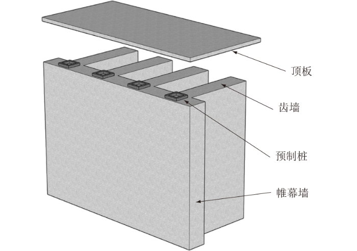
当基坑开挖深度增加或变形控制要求较严格时,增设支撑(内支撑或锚杆)可以降低结构内力及控制变形[2],但内支撑不利于坑内开挖及地下结构施工,锚杆的支护性能与锚固段长度正相关[3],存在影响或污染坑外地下空间等问题。因此,参考复合桩墙支护中墙后竖向小桩减载作用机制[4],在预制桩帷幕一体化结构中增设与帷幕墙相同工艺的齿墙[5](如图1所示),可降低支护结构土压力,提升支护性能。作为一种新型一体化支护形式,其力学机理相较于传统支护方式更为复杂,尽管复合支护技术已取得一定进展,但是针对预制桩帷幕一体化支护齿墙减载作用仍停留于定性描述,缺乏量化计算与分析,这不利于该类支护的合理化设计与推广应用。
图1 有齿墙的预制桩帷幕一体化支护结构示意图

Fig.1 Schematic diagram of integrated support structure of precast piles with dentiform curtains

目前国内外众多学者对墙后土压力计算方法进行了研究。Karah首次采用水平薄层微分方法计算刚性墙体墙后土压力[6],以砂土为研究对象,建立薄层单元静力平衡方程,获得土压力微分表达式。涂兵雄等[7]以黏性填土为研究对象,考虑墙后土拱效应,采用薄层微分法推导出主动土压力系数和主动土压力解析解,解决了薄层微分理论只能计算砂性土土压力的问题。刘忠玉等[8]考虑水平层间的剪应力,以墙后无黏性土为研究对象,假设土拱为圆弧形,修正薄层微分法理论,推导出平动模式下土压力分布曲线。Wang等[9]考虑土拱效应,将改进差分薄层单元法与伪静力法相结合,推导了平动模式下地震活动土压力的理论公式。蒋峻峰等[10]针对黏性土,考虑墙土摩擦角、墙顶张拉裂缝高度、墙体位移状态及折线滑移面对土压力的影响,改进了库伦土压力理论。陈建旭等[11]考虑土拱效应,根据虚功原理得到倾斜挡墙黏性填土非极限主动土压力表达式。
墙后土体滑裂面模式是土压力计算的前提,常规库伦直线滑裂面与实际土体滑动情况不甚相符。基于此,众多学者针对滑裂面模式展开了大量的研究与探讨。Ellis[12]假定沟堑滑裂面为旋轮线,推导了土体安全度与临界坡度的解析解,计算结果良好,据此认为墙后土体在极限状态下的滑裂面为旋轮线。曹振民[13]对墙后土体处于主动土压力状态时,滑裂面为直线和旋轮线这两种假定的合理性进行对比分析,并推出旋轮线滑裂面土压力分布曲线和土压力作用点的计算公式。徐杨等[14]基于塑性分析理论,分别推导出直线型和对数螺旋线型滑裂面滑移模式下主动土压力计算公式,以此来研究滑裂面形状对墙后土压力的影响。杨和平等[15]从工程实际出发,针对目前挡墙土压力计算手册方法不适合填黏土路堤墙的现状,考虑墙顶黏性土开裂的影响,提出采用旋轮线滑裂面路堤墙黏性回填土的主动土压力分析方法,并通过算例进行验证。
针对预制桩帷幕一体化支护,本文提出基于旋轮线滑裂面与水平薄层微分理论的齿墙减载作用计算分析方法,并以此计算分析齿墙结构参数、土体参数、墙土界面参数对墙后土压力减载作用的影响规律,揭示齿墙减载作用的关键机制。本文研究解决了预制桩帷幕一体化支护齿墙减载作用难以量化的问题,可为实际工程中该类支护结构优化设计提供理论依据。

1 墙后土压力计算方法

1.1 基本假定

(1)墙后土体为各向同性均质土。
(2)只考虑齿墙侧壁及后壁对土体的竖向摩擦减载作用,不考虑水平向的摩阻力,将齿墙本身视为均质土体,其本身所提供的侧向抗力作为安全储备。
(3)作用于齿墙侧壁及后壁的法向应力为静止土压力。
(4)黏聚力c、内摩擦角φ为常数,不考虑水的渗透压力。
(5)将破坏土楔体视作刚体,不考虑滑动土楔体内部的应变和应力条件。

1.2 旋轮线滑裂面模式

依托安阳某基础设施建设项目基坑支护工程,考虑对称性建立二分之一的简化模型,模型x、y、z方向长度分别为80、5.4、40 m。边界条件为:模型上部为自由面;侧面为法向约束;底部每个方向均建立约束。土体采用小应变硬化(Hardening Soil Small-strain,HSS)本构模型,计算参数如表1所示。支护结构采用线弹性模型,参考文献[16],根据刚度等效原则将围护墙中预制管桩等效为厚度0.287 m板单元模拟,弹性模量取为38 GPa,重度为25 kN/m3,泊松比为0.2;水泥土幕墙及齿墙采用线弹性模型,其弹性模量为300 MPa,重度为19 kN/m3。
表1 土层物理力学参数

Table 1 Physical and mechanical parameters of soil layer

地层
名称
重度γ/
(kN·m-3)
黏聚力
c/kPa
内摩擦角
φ/(°)
标准固结试验
参考切线模量
/MPa
三轴排水试验
参考割线模量
/MPa
三轴排水加卸
载试验参考卸
载模量/MPa
初始剪切
模量
/MPa
剪切模量衰减
至0.7倍时的剪
应变/10-6
粉质黏土 18.5 6 26 4.21 5.22 40.58 109.6 2
经过强度折减法计算,当墙后土体处于极限状态时,基于塑性点分布(如图2所示),墙后土体破坏滑裂面为墙底延伸至地面的一条曲线。
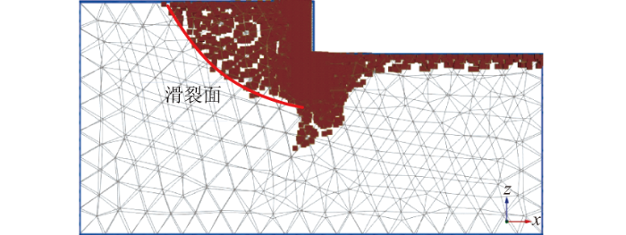
图2 支护作用下塑性点分布

Fig.2 Distribution of plasticity point under support action

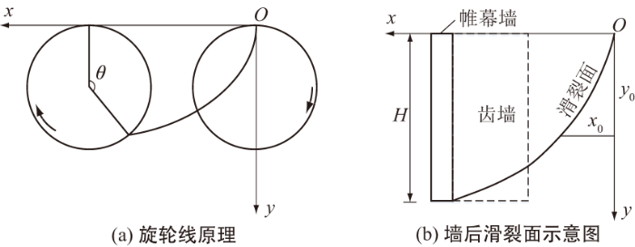
目前,基于曲线滑裂面进行土压力计算主要分为对数螺旋线型、旋轮线型、圆弧型等。与圆弧型相比,旋轮线更符合墙后土体实际滑裂面,且通过几何参数旋轮半径R、旋轮转角θ定义滑裂面形状,相比对数螺旋线迭代计算更便捷。Ellis[12]、曹振民[13]、杨贵等[17]众多学者采用旋轮线型进行研究,取得了令人较为满意的结果。综合考虑墙后土体破坏形态及计算效率,本文将墙后滑裂面假定为旋轮线型滑裂面,如图3所示。
图3 旋轮线滑裂面假定

Fig.3 Assumption of cycloidal slip surface

在直角坐标系xOy中,旋轮线型滑裂面的数学方程为:
$x=R\left(\theta -\mathrm{s}\mathrm{i}\mathrm{n}\theta \right) ,$
$y=R\left(1-\mathrm{c}\mathrm{o}\mathrm{s}\theta \right) 。$
由图3(b)可知,当旋轮线经过墙底时,旋轮转角为θc,y=H,H为帷幕墙高度,则旋轮半径R为
$R=H/\left(1-\mathrm{c}\mathrm{o}\mathrm{s}{\theta }_{\mathrm{c}}\right) 。$
则滑裂面上任一点处的θ为
$\theta =\mathrm{a}\mathrm{r}\mathrm{c}\mathrm{c}\mathrm{o}\mathrm{s}\left(1-y/R\right) 。$
假设旋轮线上任一点斜率k为
$k=\frac{\mathrm{d}y}{\mathrm{d}x}=\frac{R\mathrm{s}\mathrm{i}\mathrm{n}\theta \mathrm{d}\theta }{R\left(1-\mathrm{c}\mathrm{o}\mathrm{s}\theta \right)\mathrm{d}\theta }=\mathrm{t}\mathrm{a}\mathrm{n}\frac{\mathrm{\pi }-\theta }{2} 。$

1.3 土压力计算

滑裂面为旋轮线时帷幕墙后土压力计算简化模型如图4所示。
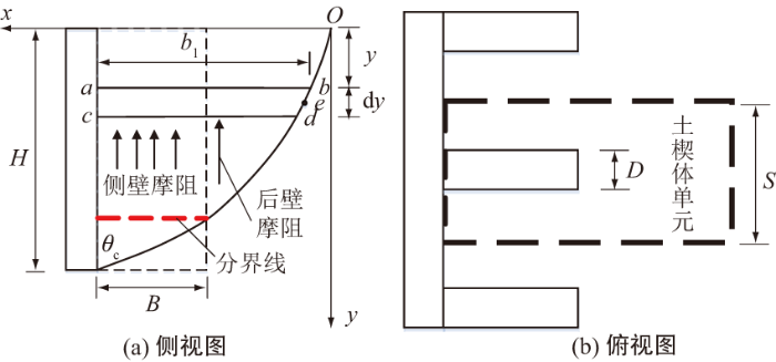
图4 齿形帷幕预制桩一体化支护旋轮线滑裂面分析示意图

Fig.4 Graphical representation of cycloidal slip fracture surface analysis for integrated support of precast piles with dentiform curtains

设帷幕墙高为H,齿墙间距为S,齿墙宽度为B,齿墙厚度为D;填土重度为γ,黏聚力为c,内摩擦角为φ;墙土间黏聚力为c1,外摩擦角为δ,静止土压力系数为k0。以齿墙间距S为一个计算单元进行分析,如图4所示。
其中,任意深度处的薄层微分单元上界面长度b1为
${b}_{1}=\frac{H\left({\theta }_{\mathrm{c}}-\mathrm{s}\mathrm{i}\mathrm{n}{\theta }_{\mathrm{c}}\right)}{1-\mathrm{c}\mathrm{o}\mathrm{s}{\theta }_{\mathrm{c}}}-\frac{y\left(\theta -\mathrm{s}\mathrm{i}\mathrm{n}\theta \right)}{1-\mathrm{c}\mathrm{o}\mathrm{s}\theta } 。$
则薄层土体重力为(略去二阶微量)
$\mathrm{d}w=\frac{\gamma }{2}\left({b}_{1}+{b}_{1}-\mathrm{t}\mathrm{a}\mathrm{n}\frac{\theta }{2}\mathrm{d}y\right)\mathrm{d}yS=\gamma {b}_{1}S\mathrm{d}y 。$
由图4(a)可知,以齿墙后壁与滑裂面交点处水平线为分界线,该分界线以上,即当b1>B时,墙后土楔体受齿墙侧壁摩阻力和齿墙后壁摩阻力的减载作用;该分界线以下,即当b1≤B时,墙后土楔体仅受齿墙侧壁摩阻力的减载作用。因此,将该分界线上下两侧土压力分开计算。
当b1>B时,取薄层微分单元abcd进行受力分析,如图5所示,其中f1、f2分别为所受齿墙侧壁和齿墙后壁竖直向上的摩阻力,q、q+dq分别为薄层微分单元所受的上下均布力,P、P1分别为薄层微分单元左右两侧所受的合力。
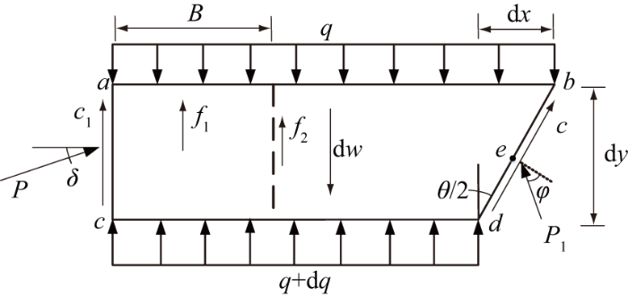
图5 分界线以上薄层微分单元受力分析示意图

Fig.5 Schematic diagram of force analysis of thin-layer differential unit above boundary line

建立土体薄层微分单元在x、y方向的受力平衡方程,化简后则有
$\mathrm{d}q=\gamma \mathrm{d}y+\left(Nq-cV-{c}_{1}{V}_{1}-PG-Ty\right)\frac{\mathrm{d}y}{{b}_{1}} 。$
其中:
$N=\mathrm{t}\mathrm{a}\mathrm{n}\frac{\theta }{2} ,$
$V=\mathrm{t}\mathrm{a}\mathrm{n}\frac{\theta }{2}\mathrm{t}\mathrm{a}\mathrm{n}\left(\frac{\theta }{2}+\varphi \right)+1 ,$
${V}_{1}=1+\frac{2B\mathrm{c}\mathrm{o}\mathrm{s}\frac{\theta }{2}+D}{S} ,$
$G=\mathrm{s}\mathrm{i}\mathrm{n}\delta +\mathrm{c}\mathrm{o}\mathrm{s}\delta \mathrm{t}\mathrm{a}\mathrm{n}\left(\frac{\theta }{2}+\varphi \right) ,$
$T=\frac{{k}_{0}\gamma \mathrm{t}\mathrm{a}\mathrm{n}\delta \left(2B\mathrm{c}\mathrm{o}\mathrm{s}\frac{\theta }{2}+D\right)}{S} 。$
对土体薄层微分单元滑裂面中点e进行力矩平衡分析并化简,则有
$P=Mq-Qc+{Q}_{1}{c}_{1}+Jy 。$
其中:
$M=\frac{\mathrm{t}\mathrm{a}\mathrm{n}\frac{\theta }{2}}{\mathrm{c}\mathrm{o}\mathrm{s}\delta \mathrm{t}\mathrm{a}\mathrm{n}\left(\frac{\theta }{2}+\varphi \right)-\mathrm{s}\mathrm{i}\mathrm{n}\delta } ,$
$Q=\frac{\mathrm{t}\mathrm{a}\mathrm{n}\frac{\theta }{2}\mathrm{t}\mathrm{a}\mathrm{n}\left(\frac{\theta }{2}+\varphi \right)+1}{\mathrm{c}\mathrm{o}\mathrm{s}\delta \mathrm{t}\mathrm{a}\mathrm{n}\left(\frac{\theta }{2}+\varphi \right)-\mathrm{s}\mathrm{i}\mathrm{n}\delta } ,$
${Q}_{1}=\frac{S{b}_{1}-{b}_{1}\left(2B\mathrm{c}\mathrm{o}\mathrm{s}\frac{\theta }{2}+D\right)+\left(2{B}^{2}\mathrm{c}\mathrm{o}\mathrm{s}\frac{\theta }{2}+2BD\right)}{S{b}_{1}\left[\mathrm{c}\mathrm{o}\mathrm{s}\delta \mathrm{t}\mathrm{a}\mathrm{n}\left(\frac{\theta }{2}+\varphi \right)-\mathrm{s}\mathrm{i}\mathrm{n}\delta \right]} ,$
$J=\frac{{k}_{0}\gamma \mathrm{t}\mathrm{a}\mathrm{n}\delta \left[{b}_{1}\left(2B\mathrm{c}\mathrm{o}\mathrm{s}\frac{\theta }{2}+D\right)-\left(2{B}^{2}\mathrm{c}\mathrm{o}\mathrm{s}\frac{\theta }{2}+2BD\right)\right]}{S{b}_{1}\left[\mathrm{c}\mathrm{o}\mathrm{s}\delta \mathrm{t}\mathrm{a}\mathrm{n}\left(\frac{\theta }{2}+\varphi \right)-\mathrm{s}\mathrm{i}\mathrm{n}\delta \right]}。$
将式(14)代入式(8)得
$\begin{array}{l}\frac{\mathrm{d}q}{\mathrm{d}y}=\gamma +\frac{1}{{b}_{1}}[\left(N-GM\right)q+\left(GQ-V\right)c-\\ \left({V}_{1}+{Q}_{1}G\right){c}_{1}-\left(GJ+T\right)y] 。\end{array}$
当b1≤B时,土体薄层微分单元a'b'c'd'受力分析如图6所示,此时仅受齿墙侧壁竖直向上的摩阻力f1。
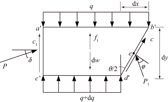
图6 分界线以下薄层微分单元受力分析示意图

Fig.6 Schematic diagram of force analysis of thin-layer differential unit below boundary line

建立土体薄层微分单元在x、y方向的受力平衡方程并计算,化简后则有
$\mathrm{d}q=\gamma \mathrm{d}y+\frac{\mathrm{d}y}{{b}_{1}}(Nq-cV-{c}_{1}{V\text{'}}_{1}-PG-T\text{'}y) 。$
其中:
${V\text{'}}_{1}=1+\frac{2{b}_{1}\mathrm{c}\mathrm{o}\mathrm{s}\frac{\theta }{2}}{S} ,$
$T\text{'}=\frac{2{b}_{1}{k}_{0}\gamma \mathrm{t}\mathrm{a}\mathrm{n}\delta \mathrm{c}\mathrm{o}\mathrm{s}\frac{\theta }{2}}{S} 。$
对土体薄层微分单元滑裂面中点e进行力矩平衡分析并化简,则有
$P=Mq-Qc+{Q\text{'}}_{1}{c}_{1} 。$
其中:
${Q\text{'}}_{1}=\frac{1}{\mathrm{c}\mathrm{o}\mathrm{s}\delta \mathrm{t}\mathrm{a}\mathrm{n}\left(\frac{\theta }{2}+\varphi \right)-\mathrm{s}\mathrm{i}\mathrm{n}\delta } 。$
将式(23)代入式(20)得
$\begin{array}{l}\frac{\mathrm{d}q}{\mathrm{d}y}=\gamma +\frac{1}{{b}_{1}}[\left(N-GM\right)q+\left(GQ-V\right)c-\\ \left({V\text{'}}_{1}+{Q\text{'}}_{1}G\right){c}_{1}-T\text{'}y] 。\end{array}$
上述式(14)及式(23)即为支护结构土压力计算表达式。若墙后滑动土体分为n个薄层,根据上述公式求解各薄层P值,则土压力合力Ea为
${E}_{\mathrm{a}}=\stackrel{n}{\sum _{i=1}}{P}_{i}\mathrm{d}y 。$
各薄层P作用点距墙底的高度为z,合力作用点距墙底的高度$\stackrel{-}{z}$为
$\stackrel{-}{z}=\frac{\stackrel{n}{\sum _{i=1}}{P}_{i}{z}_{\mathrm{i}}}{\stackrel{n}{\sum _{i=1}}{P}_{i}} 。$
采用墙后滑动土体划分水平薄层,通过MATLAB软件进行编程,设定θc在(0,π)中变化,循环计算搜索土压力合力最大值Emax,即为墙后土体滑动条件下墙背承受的土压力,对应的旋轮转角θc即为临界旋转角,此时,根据各薄层土压力计算值可绘制出土压力沿深度方向分布曲线。

1.4 算例验证
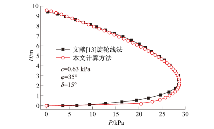
取文献[13]算例,帷幕墙高H=10 m,土体重度γ=16 kN/m3,墙后土体表面荷载边界为0,令参数B、D为0,θc在(0,π)中变化,步长为1°进行循环计算,将计算结果与文献[13]中墙背倾角α为0时的计算结果进行对比,如图7及表2所示。
图7 2种计算方法结果对比

Fig.7 Comparison of results of two calculation methods

表2 不同δ、φ下两种计算方法结果对比

Table 2 Comparison of results of two calculation methods under different δ and φ

δ/
(°)
φ/
(°)
文献[13]计算结果 本文计算结果
θc/
(°)
Ea/
(kN·m-1)
z/
m
Ea/
(kN·m-1)
z/
m
10 30 80 236.55 3.603 234.88 3.638
15 35 74 190.78 3.723 190.23 3.796
10 35 72 191.92 3.562 190.43 3.617
由图7及表2可知,本文计算得到的土压力分布、土压力合力Ea及合力作用点距墙底的高度z随δ、φ的变化规律与文献[13]相应的计算结果近乎吻合,数值上略有差异,这与编程计算过程计算步划分的精细度有关。由此验证了本文计算公式推导的正确性及编程计算的可行性。

2 齿墙减载作用计算与分析

2.1 齿墙结构参数影响分析

参考表1的场地条件,保持土体参数不变(γ=18.5 kN/m3、 c=6 kPa、 φ=26°、 c1=3.6 kPa、 δ=15.6°),结合实际工程应用及基坑支护规范[18],分别变化齿墙间距S、齿墙宽度B、齿墙厚度D,计算分析齿墙结构参数对齿墙减载作用的影响规律。

2.1.1 齿墙间距的影响

保持B=2 m、D=0.8 m不变,计算得到不同齿墙间距S(1.2、1.8、2.4、3.0 m,为预制桩径d的2~5倍)对应的土压力及相对无齿墙时的减载比例,如图8所示。可见,由于齿墙对围护墙后滑动土体的竖向摩阻作用,相较于无齿墙时,增加齿墙后的土压力显著减小。齿墙间距由1.2 m增大至3.0 m时,由于齿墙分担的土体范围增大,极限状态下围护墙土压力由139.16 kN/m增大至189.51 kN/m,齿墙减载比例由44.02%减小至23.77%。随着齿墙间距增大,减载比例减小幅度有变缓的趋势,但过大的齿墙间距将削弱齿墙间土体的约束,使得其局部土压力较大,这不利于齿墙间土体的安全稳定,对支护体系而言,也失去了减载的作用。综合工程安全性及经济性,建议齿墙间距在3d~5d范围内。
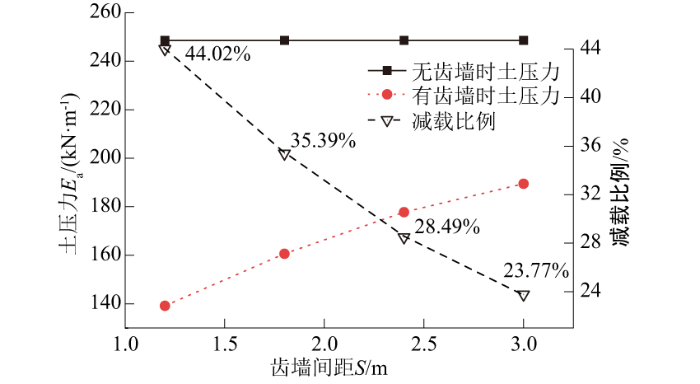
图8 不同S下土压力计算结果及减载比例

Fig.8 Calculation results of soil pressure and load reduction ratio under different values of S

2.1.2 齿墙宽度的影响

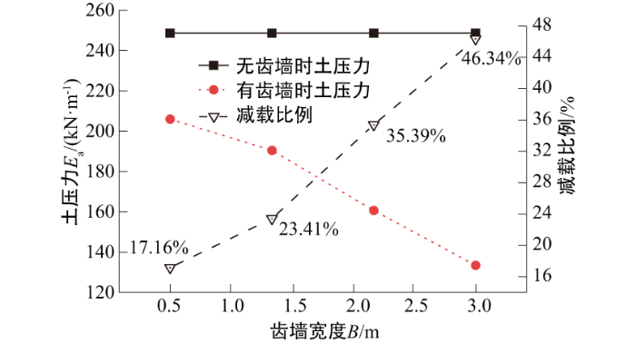
保持S=1.8 m、D=0.8 m不变,计算得到不同齿墙宽度B(0.5、1、2、3 m)对应的土压力及相对无齿墙时的减载比例,如图9所示。由图9可见,随着齿墙宽度由0.5 m增大至3 m,极限状态下土压力逐渐减小,由205.96 kN/m减小至133.41 kN/m,减载比例由17.16%增大至46.34%,这是由于宽度B的增加所引起的齿墙侧壁与滑动土体间的接触面积增大,减载作用随之增强。
图9 不同B下土压力计算结果及减载比例

Fig.9 Calculation results of soil pressure and load reduction ratio under different values of B

2.1.3 齿墙厚度的影响

保持S=1.8 m、B=2 m不变,计算得到不同齿墙厚度D(0.4、0.6、0.8、1.0 m)对应的土压力及相对无齿墙时的减载比例,如图10所示。由图10可知,齿墙厚度由0.4 m增大至1.0 m时,土压力由167.42 kN/m减小至157.46 kN/m,减载比例由32.66%增大至36.66%,呈线性增长。表明随齿墙厚度增大,尽管土压力存在逐渐减小的趋势,但减载效果增幅有限。增加齿墙厚度,增大了齿墙后壁与滑动土体的接触面积,但由于齿墙具有一定的宽度,滑裂面延伸至齿墙后壁时位置较高,滑动土体与齿墙后壁实际作用面积受限(图4(a)),且实际应用中齿墙厚度亦受到支护结构一体化设计及施工工艺的限制,致使增加墙厚对齿墙减载作用提升比较有限。
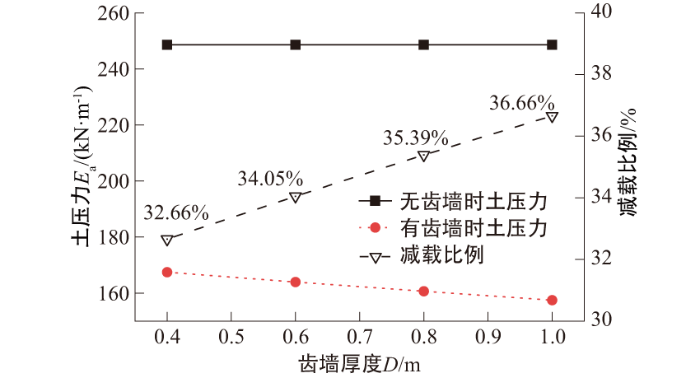
图10 不同D下土压力计算结果及减载比例

Fig.10 Calculation results of soil pressure and load reduction ratio under different values of D

2.2 土体强度参数影响分析

保持齿墙结构参数不变(S=1.8 m、D=0.8 m、B=2 m),分别变化土体黏聚力c、内摩擦角φ,探讨土体强度参数对齿墙减载作用的影响规律。

2.2.1 土体黏聚力的影响

保持φ=26°、c1=3.6 kPa、δ=15.6°不变,当土体黏聚力c为1、6、11、16 kPa时,有无齿墙时土压力及相应减载比例如图11所示。可见,随着黏聚力c由1 kPa增大至16 kPa时,有无齿墙土压力均逐渐减小,但齿墙的减载作用显著,减载比例由28.14%增大至59.86%,减载效果呈现逐渐提升的趋势。表明基坑所在场地的土体黏聚力较高时,增设齿墙结构可以充分发挥其减载作用。
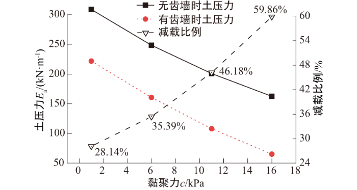
图11 不同c下土压力计算结果及减载比例

Fig.11 Calculation results of soil pressure and load reduction ratiounder different values of c

2.2.2 土体内摩擦角的影响

保持c=6 kPa、c1=3.6 kPa、δ=15.6°不变,当土体内摩擦角φ为16°、21°、26°、31°时,有无齿墙时土压力及其相应减载比例如图12所示。可知,与土体黏聚力的影响规律相似,随土体内摩擦角φ由16°增大至31°,有无齿墙土压力均逐渐减小,齿墙的减载比例由20.43%增大至42.68%,呈线性增长趋势。表明土体内摩擦角较高时同样有利于发挥齿墙的减载作用。
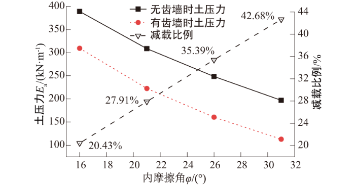
图12 不同φ下土压力计算结果及减载比例

Fig.12 Calculation results of soil pressure and load reduction ratio under different values of φ

2.2.3 土体强度参数组合的影响

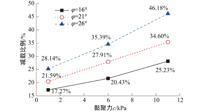
保持c1=3.6 kPa、δ=15.6°不变,当黏聚力(1、6、11 kPa)和内摩擦角(16°、21°、26°)同时变化时,不同土体强度参数组合下所对应减载比例如图13所示。可知,在黏聚力和内摩擦角同时增大时,减载比例明显提升,由17.27%增大至46.18%。此外,在高黏聚力c条件下,增大内摩擦角φ,齿墙减载比例提升更显著。
图13 不同c、φ组合下齿墙减载比例变化

Fig.13 Variation of load reduction ratio under different combinations of c and φ

2.3 墙土界面参数影响分析

保持齿墙结构参数不变(S=1.8 m、D=0.8 m、B=2 m),分别变化齿墙与土体的界面黏聚力和外摩擦角,研究墙土界面参数对齿墙减载作用的影响规律。

2.3.1 墙土界面黏聚力的影响

保持c=6 kPa、φ=26°、δ=15.6°不变,当墙土间黏聚力c1为0.6、3.6、6.6、9.6 kPa时,有无齿墙时土压力及其减载比例如图14所示。可见,随着墙土间黏聚力c1逐渐由0.6 kPa增大至9.6 kPa,存在齿墙时,土压力减小更为显著,齿墙的减载比例27.41%增大至50.41%,呈线性增长趋势。因此,采用合适的材料或施工工艺,提升墙土间的黏结作用,将有利于齿墙减载作用的发挥。
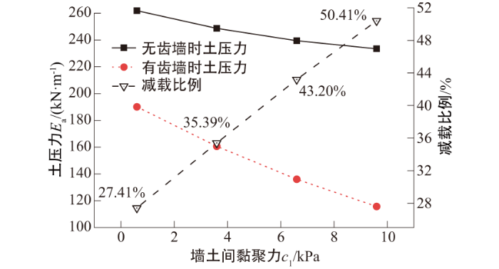
图14 不同c1下土压力计算结果及减载比例

Fig.14 Calculation results of soil pressure and load reduction ratio under different values of c1

2.3.2 墙土界面摩擦角的影响

保持c=6 kPa、c1=3.6 kPa、φ=26°不变,当墙土间外摩擦角δ为9.6°、12.6°、15.6°、18.6°时,有无齿墙时土压力及其减载比例如图15所示。可见,随着墙土间外摩擦角δ由9.6°增大至18.6°,土压力有所减小,齿墙的减载比例由30.33%增大至36.21%,虽有增大趋势,但提升相对较小,且随着δ增大,减载比例增长幅度逐渐变缓。
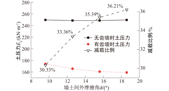
图15 不同δ下土压力计算结果及减载比例

Fig.15 Calculation results of soil pressure and load reduction ratio under different values of δ

3 结论

本文针对预制桩帷幕一体化支护,基于旋轮线滑裂面假定与水平薄层微分理论,建立了墙后土体在滑动条件下齿墙对围护结构土压力的减载作用计算方法,并计算分析了相关设计参数影响规律。主要结论如下:
(1)提出的计算方法有效解决了预制桩帷幕一体化支护存在齿墙时土压力难以量化分析的问题。计算表明,齿墙具有显著的减载作用,对墙后滑动土体土压力的减载比例可达到50%以上。
(2)减小齿墙间距S、增大齿墙宽度B均可显著提升减载效果;由于齿墙具有一定宽度,齿墙后壁与滑动土体接触面积受限,齿墙厚度D的增加对减载效果的提升不明显。
(3)墙后土体的黏聚力c、内摩擦角φ的增大均能显著增加齿墙的减载比例,表明在土质条件较好的场地,增设齿墙对预制桩帷幕一体化支护性能的提升更为有利;墙土间作用强度增加也有助于增大齿墙的减载比例,但墙土间黏聚力c1的增大影响相对更显著。
本文研究适用于单一土层且地下水位较低或渗透性较弱的地层,非均质性(如分层、夹层、软硬交替)以及高水位或渗透性较强的地层中局部软弱层可能引发应力集中,影响土压力分布及减载效果的规律性。针对复杂地层(如分层土、含软弱夹层土体),后续可结合数值模拟或原位试验,对比“等效参数修正”和“改进分层滑裂面模式”等方法,进一步探究齿墙减载作用变化规律,并考虑高水压及渗流作用,引入渗透参量和孔隙水压力优化齿墙减载作用的预测。
[1]
孙超, 郭浩天. 深基坑支护新技术现状及展望[J]. 建筑科学与工程学报, 2018, 35(3): 104-117.

(Sun Chao, Guo Hao-tian. Present Situation and Prospect of New Technology for Deep Foundation Pit Support[J]. Journal of Architecture and Civil Engineering, 2018, 35(3): 104-117. (in Chinese))

[2]
孙雅珍, 尹方东, 叶翔, 等. 基坑开挖对在建道路的影响及加固措施[J]. 沈阳建筑大学学报(自然科学版), 2024, 40(1):114-122.

(Sun Ya-zhen, Yin Fang-dong, Ye Xiang, et al. Study on Influence of Foundation Pit Excavation on Road under Construction and Reinforcement Measures[J]. Journal of Shenyang Jianzhu University (Natural Science), 2024, 40(1): 114-122. (in Chinese))

[3]
李兵, 刘阳, 李卓伦, 等. 锚杆参数对深基坑变形影响的有限元分析[J]. 沈阳建筑大学学报(自然科学版), 2020, 36(3):404-411.

(Li Bing, Liu Yang, Li Zhuo-lun, et al. Finite Element Analysis of Influence of Bolt Parameters on Deformation of Deep Foundation Pit[J]. Journal of Shenyang Jianzhu University (Natural Science), 2020, 36(3): 404-411. (in Chinese))

[4]
童怀峰, 锁利军. 复合桩墙锚支护技术在深基坑中的应用[J]. 水电能源科学, 2010, 28(10): 90-92.

(Tong Huai-feng, Suo Li-jun. Application of Compound Anchored Pile Wall Support Technique to Deep Foundation Pit[J]. Water Resources and Power, 2010, 28(10): 90-92. (in Chinese))

[5]
李永辉, 周同和, 邹会芳, 等. 一种齿形帷幕预制桩围护结构及施工方法:CN202310041240.5[P].2023-06-23.

(Li Yong-hui, Zhou Tong-he, Zou Hui-fang, et al. A kind of Dentiform Curtain Precast Pile Enclosure Structure and Construction Method: CN202310041240.5[P]. 2023-06-23. (in Chinese))

[6]
顾慰慈. 挡土墙土压力计算[M]. 北京: 中国建材工业出版社, 2001: 167-378.

(Gu Wei-ci. Earth Pressure Calculation of Retaining Wall[M]. Beijing: China Building Materials Industy Press, 2001: 167-378. (in Chinese))

[7]
涂兵雄, 贾金青. 考虑土拱效应的黏性填土挡土墙主动土压力研究[J]. 岩石力学与工程学报, 2012, 31(5):1064-1070.

(Tu Bing-xiong, Jia Jin-qing. Research on Active Earth Pressure Behind Rigid Retaining Wall from Clayey Backfill Considering Soil Arching Effects[J]. Chinese Journal of Rock Mechanics and Engineering, 2012, 31(5): 1064-1070. (in Chinese))

[8]
刘忠玉, 陈捷, 李东阳. 考虑剪应力作用的刚性挡土墙主动土压力分析[J]. 岩土力学, 2016, 37(9): 2443-2450.

(Liu Zhong-yu, Chen Jie, Li Dong-yang. Calculation of Active Earth Pressure Against Rigid Retaining Wall Considering Shear Stress[J]. Rock and Soil Mechanics, 2016, 37(9): 2443-2450. (in Chinese))

[9]
Wang Z Z, Kou R C, Zhou Y, et al. Simplified Calculation Method for Seismic Active Earth Pressure of Translational Retaining Wall Considering Soil Arching Effect[J]. Shock and Vibration, 2021, 2021: 6713032.

DOI

[10]
蒋峻峰, 赵其华, 喻小, 等. 挡土结构墙后黏土主动土压力改进计算[J]. 长江科学院院报, 2021, 38(2):80-85,91.

DOI

(Jiang Jun-feng, Zhao Qi-hua, Yu Xiao, et al. An Improvement on Calculating Active Earth Pressure of Cohesive Soil Behind Retaining Structure[J]. Journal of Changjiang River Scientific Research Institute, 2021, 38(2): 80-85, 91. (in Chinese))

[11]
陈建旭, 钱波, 郭宁, 等. 倾斜挡墙黏性填土非极限主动土压力计算[J]. 长江科学院院报, 2021, 38(12):137-145.

DOI

(Chen Jian-xu, Qian Bo, Guo Ning, et al. Calculation of Non-limit Active Earth Pressure on Cohesive Backfill of Inclined Retaining Wall[J]. Journal of Yangtze River Scientific Research Institute, 2021, 38(12): 137-145. (in Chinese))

DOI

[12]
Ellis H B. Use of Cycloidal Arcs for Estimating Ditch Safety[J]. Journal of the Soil Mechanics and Foundations Division, 1973, 99(2): 165-179.

DOI

[13]
曹振民. 挡土墙填土曲线破裂面主动土压力分析[J]. 中国公路学报, 1995, 8(增刊1): 7-14.

(Cao Zhen-min. Analysis of Active Earth Pressure of back Fill on Retaining Wall with Curved Rupture Surface[J]. China Journal of Highway and Transport, 1995, 8(Supp.1):7-14. (in Chinese))

[14]
徐杨, 阎长虹, 姜玉平, 等. 滑裂面形状对挡土墙主动土压力的影响[J]. 煤田地质与勘探, 2015, 43(4):69-74.

(Xu Yang, Yan Chang-hong, Jiang Yu-ping, et al. Effect of Slip Surface Shape on Active Earth Pressure Upon Retaining Wall[J]. Coal Geology & Exploration, 2015, 43(4): 69-74. (in Chinese))

[15]
杨和平, 林琳. 黏性填土重力式路堤墙曲线破裂面主动土压力分析[J]. 长沙理工大学学报(自然科学版), 2019, 16(1):1-9,57.

(Yang He-ping, Lin Lin. Analysis on Active Earth Pressure of Gravity Embankment Wall of Cohesive Backfill with Curved Failure Surface[J]. Journal of Changsha University of Science and Technology (Natural Science), 2019, 16(1): 1-9, 57. (in Chinese))

[16]
王恩钰, 周海祚, 郑刚, 等. 基坑倾斜桩支护的变形数值分析[J]. 岩土工程学报, 2019, 41(增刊1): 73-76.

(Wang En-yu, Zhou Hai-zuo, Zheng Gang, et al. Numerical Analyses of Deformation of Inclined Pile-retained Excavations[J]. Chinese Journal of Geotechnical Engineering, 2019, 41(Supp.1): 73-76. (in Chinese))

[17]
杨贵, 王阳阳, 刘彦辰. 基于曲线滑裂面的挡墙主动土压力分析[J]. 岩土力学, 2017, 38(8): 2182-2188.

(Yang Gui, Wang Yang-yang, Liu Yan-chen. Analysis of Active Earth Pressure on Retaining Walls Based on Curved Sliding Surface[J]. Rock and Soil Mechanics, 2017, 38(8): 2182-2188. (in Chinese))

[18]
JGJ120—2012,建筑基坑支护技术规程[S]. 北京: 中国建筑工业出版社, 2012.

(JGJ 120—2012,Technical Specification for Retaining and Protection of Building Foundation Excavations[S]. Beijing: China Architecture and Building Press, 2012. (in Chinese))

Outlines

/

〈 〉